Synchronized hydraulic system with open-loop control
Open-loop control of the hydraulic synchronous drive, rely entirely on the precision of the hydraulic control elements (such as synchronous valves, various types of throttle valves or speed control valves) itself to control the synchronization of the actuator, without the output of the actuator to detect and feedback to form a closed-loop control, so it can not be eliminated or suppressed on the high-precision synchronization of the influence of unfavorable factors, which also greatly limits the scope of application of this type of control, but the open-loop However, the open-loop control system is simple in structure and low in cost, so it is used in the occasions which do not require a high degree of synchronization.
However, the open-loop control system is simple in structure and low in cost, so it is used in the occasions where the synchronization precision requirement is not high.
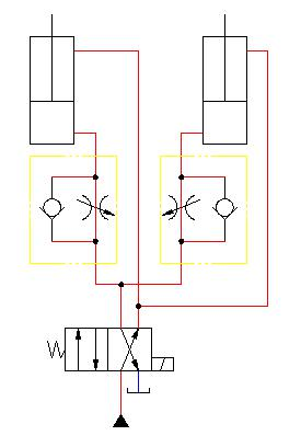
I. Throttling speed synchronization circuit
Throttling speed synchronization system of the basic principle diagram shown in Figure 1, the hydraulic cylinder single side return throttle speed circuit, the kind of Synchronization system is widely used in hydraulic systems that do not require high precision, the disadvantage is that the synchronization precision is not high, but the synchronization precision is affected by the oil temperature and load, only 5%. The disadvantage is that the synchronization accuracy is not high, but the synchronization accuracy is affected by the oil temperature and load, only up to 5%, can not be used in systems requiring higher accuracy, the synchronization system fatal The fatal disadvantage of this synchronization system is that once the opening degree of the throttle valve is adjusted, the running speed of the cylinder in the production process is determined, and it cannot be used in systems that require constant adjustment of the cylinder. Can not be used in the need to constantly adjust the cylinder speed of the system; its advantages are low cost, simple adjustment, can be multi-cylinder synchronization. Step. But the synchronization system in the actual use of the process, after a period of time after the operation of the hydraulic system, the hydraulic cylinder synchronization effect will change. Cylinder synchronization effect will change, mainly because of the fluid on the spool of the different degree of wear and tear, resulting in adjusted throttle The throttle port of the valve breaks and changes, and its flow rate changes accordingly, which leads to the cylinder is not synchronized. In order to improve
To improve the synchronization accuracy, a temperature-compensated speed control valve can be used instead of a throttle valve.
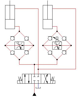
Fig. 2 Synchronization circuit using a speed control valve and a flow rectifier plate to throttle hydraulic cylinders in both directions. If a
If a proportional speed control valve is used in the oil circuit of one hydraulic cylinder, the displacement error is detected at any time during the movement of the two hydraulic cylinders by means of a detection element, and the proportional speed control valve is adjusted.
Displacement error is detected at any time during the movement of the two hydraulic cylinders through the detection element, adjust the flow rate of the proportional valve speed valve and the other hydraulic cylinder speed valve flow rate is equal, synchronization accuracy can be improved.
Fig. 1 Fig. 2
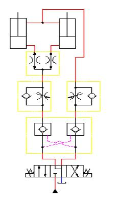
II. Shunt collector valve synchronization system
Figure 3 shows the shunt collector valve synchronization circuit, shunt collector valve synchronization system belongs to the fixed throttle port type synchronization system. In the use of the process does not need to adjust the shunt collector valve that can achieve the effect of double-cylinder synchronization, simple to use, deskewing ability, synchronization accuracy of about 1-3%, and for the need to change the cylinder speed. Powerful, synchronization accuracy of about 1%-3%, and for the need for cylinder speed change system can be used with proportional valves, and the manifold collector valve is inexpensive, and the synchronization system is a fixed throttle port synchronization system. And shunt collector valve price is cheap. Its biggest disadvantage is that it can only synchronize two cylinders, which has become a bottleneck in the application of shunt collector valve synchronization system shunt collector valve synchronization system application of a bottleneck, at the same time its synchronization control accuracy is not high, with the throttle synchronization system accuracy is similar, and the cylinder operating speed At the same time, its synchronization control accuracy is not high, similar to that of throttle synchronization system, and the running speed of the cylinder is limited by the rated flow rate of the manifold collector valve. Therefore, in this kind of circuit, it is necessary to fully consider the fastest and slowest speed of the cylinder, and it is necessary to accurately account for the flow rate of the cylinder to select the shunt collector valve, otherwise it is easy to damage the shunt collector valve. Otherwise, the shunt collector valve will be easily damaged.
The synchronization accuracy of open-loop control depends on the manufacturing accuracy of the hydraulic components. When used for a period of time, the components have different degrees of wear and tear, the hydraulic components will have a static or dynamic effect on the synchronization of the hydraulic cylinder, and at the same time, due to the perturbation of the load under different conditions, the frictional resistance generated by the cylinder movement, the leakage of hydraulic oil, the mixing of air, the performance of the control components between the differences in the circuit of each component of the manufacturing error and other factors, will have a different degree of influence on the synchronization accuracy of the hydraulic cylinder.
Different degrees of influence, and the amount of hydraulic cylinder synchronization and can not be fed back to the control of synchronous movement of the components, it relies solely on the hydraulic control components (such as a variety of valves) to control the accuracy of the synchronization of the executive element of the movement, so no matter what compensation measures taken, synchronization accuracy are lower This is the characteristics of the open-loop control synchronization system.
Shunt collector valve, also known as speed synchronization valve, is a hydraulic valve in the shunt valve, collector valve, unidirectional shunt valve, unidirectional collector valve and proportional shunt valve of the general term. Synchronous valves are mainly used in double-cylinder and multi-cylinder synchronous control hydraulic system. Usually there are many ways to achieve synchronous movement, but one of the synchronization control hydraulic system using shunt collector valve-synchronous valve has a simple structure, low cost, easy to manufacture, strong reliability and many other advantages, so synchronous valves in the hydraulic system has been widely used. Shunt collector valve synchronization is speed synchronization, when two cylinders or more cylinders are subjected to different loads, the shunt collector valve can still ensure its synchronization.
Second, the role of shunt collector valve
The role of the diverter valve is to make the hydraulic system from the same source of oil to more than two actuators to supply the same amount of flow (equal amount of shunt), or according to a certain ratio to the two executive elements supply flow (proportional shunt), in order to realize the two executive elements to maintain synchronization or constant ratio relationship. The speeds of the two actuators are synchronized or in a constant ratio.
The function of the collector valve is to collect equal flow or proportional return oil volume from the two actuators to realize the speed synchronization or constant ratio relationship between them. The function of the manifold is to collect an equal or proportional return flow from the two actuators to achieve a synchronized or constant ratio relationship between them. Diverter-collector valves have the functions of both diverter and collector valves. Their graphical symbols are shown in Figure The graphical symbols of them are shown in Fig.
1、Diverter valve (flow divider)
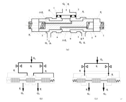
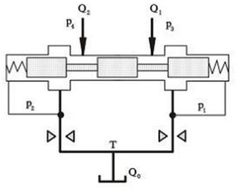
Figure 4 (a) shows the structure principle diagram of the equal flow divider, which can be regarded as a series of two pressure-reducing flow control valves combined into one. It can be seen as a combination of two series pressure-reducing flow control valves. The valve adopts "flow - differential pressure - force" negative feedback, with two equal area fixed throttle orifices 1, 2 as the flow primary Two fixed orifices 1 and 2 of equal area are used as primary sensors for the flow, which convert the two load flows Q1 and Q2 into corresponding differential pressure values ΔP1 and ΔP2, respectively. The differential pressure values ΔP1 and ΔP2, which represent the two load flows Q1 and Q2, are fed back to the common pressure reducing valve core 6. The differential pressure values ΔP1 and ΔP2, representing the two load flows Q1 and Q2, are fed back to the common regulator spool 6, where they are compared with each other to drive the spool to adjust Q1 and Q2 to equalize.
(a) Structural schematic diagram of the diverter valve; (b) Diverter valve with the throttling edge designed on the inner side; (c) Diverter valve with the throttling edge designed on the outer side.
(c) Diverter valve with throttling edge designed on the outer side
When working, set the valve inlet oil pressure is P0, flow rate is Q0, into the valve in two ways respectively through the two equal area of the fixed throttle hole 1, 2, respectively into the pressure reducing valve core annular groove a and b, and then by the two pressure reducing valve port (variable throttle port) 3, 4 through the outlet port I and Ⅱ to the two actuators, the two actuators of the load flow rate were Q1, Q2, load pressure were P3, P4, if the two actuators load is equal, then the outlet pressure P3 = P4 because the size of the two manifolds in the valve is completely symmetrical, so the output flow rate is also symmetrical, Q1 = Q2 = Q0 / Q0/. If the loads of the two actuators are equal, the outlet pressure of the diverter valve P3 = P4, because the dimensions of the two branches of the valve are completely symmetrical, so the output flow rate is also symmetrical, Q1 = Q2 = Q0/2, and P1 = P2.
When P3 ≠ P4 due to load asymmetry and P3 > P4, Q1 must be smaller than Q2, resulting in a pressure difference of ΔP1 < ΔP2, P1 > P2 at fixed orifice 1, 2 pressure difference ΔP1 < ΔP2, P1 > P2, this pressure difference feedback to the two ends of the pressure reducing valve spool 6, so that the spool in the asymmetric hydraulic pressure This pressure difference is fed back to the two ends of the pressure reducing valve core 6 so that the valve core moves left under the action of the asymmetric liquid pressure, so that the variable throttle port 3 increases and the throttle port 4 decreases, thus increasing Q1 and decreasing Q2 until Q1≈Q2.
Q1 ≈ Q2 until the spool is stabilized in a new equilibrium position. The spool stabilizes in a new equilibrium position until Q1≈Q2, i.e., the flow rates to the two actuators are equal. When the two actuators are exactly the same size, the movement speed will be synchronized.
According to the different arrangement of the throttling edge and the feedback pressure measuring surface, the manifold valve has two different structures as shown in Fig. 4(b) and (c). Structure.
2、Collector valve (flow combiner)
Figure 5 shows the principle diagram of the equal amount of collector valve, which is basically the same as the feedback mode of the manifold valve, the differences are:
(1) the diverter valve is installed in the return oil of the two actuators, the return oil flow of the two loads will be pooled together back to the oil;
(2) shunt valve of the two flow sensors total inlet pressure P0, flow sensors through the flow Q1 (or Q2) the larger the outlet pressure P1 (or Q2), the larger the outlet pressure P1 (or Q2). The larger the flow rate Q1 (or Q2) of the flow sensor, the lower the outlet pressure P1 (or P2); the two flow sensors of the manifold valve common outlet O, the flow rate Q1 (or Q2) of the flow sensor, the lower the outlet pressure. The two flow sensors of the collector valve have a common outlet O, the larger the flow rate Q1 (or Q2) of the flow sensors, the higher the inlet pressure P1 (or P2). Therefore, the pressure feedback direction of the collector valve is exactly the opposite of the diverter valve.
Therefore, the pressure feedback direction of the collector valve is exactly opposite to that of the diverter valve;
(3) The collector valve can only ensure the synchronization of the actuator when returning oil.
Fig. 5 Principle of operation of the collector valve
3、Diverter and combiner valve (flow divider and combiner) Diverter and combiner valve is also known as synchronous valve, it has the function of both diverter and combiner valve, which can ensure the synchronization of oil inlet and oil return of actuator.
Figure 6 shows the structure of the hook-type shunt and combiner valve. Shunt, because P0>P1 (or P0>P2), the pressure difference will be two hook spool 1, 2 push away, in the shunt condition, at this time the shunt variable throttle port is composed of the hook spool 1, 2 of the inner edge and the valve sleeve 5, 6 of the outer edge; set flow, because P0 < P1 (or P0 < P2), the pressure difference will be hook spool 1, 2 together, in the set flow condition, at this time the set flow variable throttle port is By the hook spool 1, 2 of the outer edge and the valve sleeve 5, 6 of the inner edge of the composition.
(a) Structural diagram; (b) Operating principle when diverting flow; (c) Operating principle when collecting flow
According to the adjustment mode is divided into: fixed shunt collector valve, self-adjusting shunt collector valve, adjustable shunt collector valve, and the combination of self-adjusting and adjustable combination of adjustable shunt collector valve. and self-adjusting and adjustable combination of the combination of adjustable shunt collector valve. The above series of hydraulic valves can be designed as small flow diverter-collector valves. The above series of hydraulic valves can be designed as small flow diverter-collector valves. Among them, the fixed structure synchronous valve can be divided into commutative piston type and hook type two kinds of structure. This series of hydraulic valves according to This series of hydraulic valves can also be divided into equal flow type manifold and proportional flow type manifold according to the flow distribution method, and the ratio often used is 2. 1: It can also be designed as a small flow synchronization valve according to the required ratio.
Fourth, the difference between collector valve and diverter valve
Difference between collector valve and diverter valve:
(1) the collector valve is installed in the return oil of the two executive elements, the return oil flow of the two loads will be pooled together back to the oil;
(2) Diverter valve of the two flow sensors total inlet pressure, flow sensors through the flow rate of the larger, its outlet pressure On the contrary, the lower; collector valve of the two flow sensors common outlet, the flow sensor through the flow rate is larger, its inlet pressure is higher. The higher the flow rate of the flow sensor, the higher the inlet pressure. Therefore, the pressure feedback direction of the collector valve is exactly the opposite of the manifold valve;
(3) The collector valve can only ensure the synchronization of the actuator when returning oil.
Summary of this section
The synchronization accuracy of open-loop control depends on the manufacturing accuracy of the hydraulic components. Take the shunt throttle valve and the collector throttle valve as an example. Comparative analysis.


 8617862265069
  info@cndieselpart.com
  English