Synchronized hydraulic system with closed-loop control
When the hydraulic synchronization closed-loop control system can be used to detect the output of the actuator, feedback, and with the input signal Comparison, thus constituting a negative feedback closed-loop control. Although the system composition is complex, into the wood high, but can eliminate and inhibit the The influence of many unfavorable factors in the open-loop control system.
I. Classification
1, according to the realization of the task (or control output), hydraulic synchronization closed-loop control can be divided into force synchronization closed-loop control, speed synchronization closed-loop control and synchronization closed-loop control. system, speed synchronization closed-loop control and position synchronization closed-loop control.
2, according to the number of different controlled actuators, hydraulic synchronous closed-loop control and dual-actuator and multiple actuators Synchronized closed-loop control.
3、According to the type and structure of the controlled actuator, the installation form and the different direction of movement, the hydraulic synchronized closed-loop control is divided into hydraulic cylinder synchronized closed-loop control system is divided into hydraulic cylinder synchronous closed-loop control and hydraulic motor synchronous closed-loop control. Second, the control principle and method The basic principle of closed-loop control is the use of feedback detection components of the control system output signal and input signal for the Comparison of the output signal of the control system and the input signal, and make it smaller. The control principle is shown in Figure 7.
Fig. 7 Closed-loop control principle diagram
However, the purpose of hydraulic synchronized closed-loop control is to synchronize the outputs of multiple actuators and loads with high precision. For hydraulic synchronized closed-loop control, "equal mode" and "master-slave mode" are the two control strategies usually adopted. For hydraulic synchronized closed-loop control, "equal method" and "master-slave method" are the two control strategies usually adopted. For hydraulic synchronized closed-loop control, "equal approach" and "master-slave approach" are the two control strategies commonly used. The "master-slave method" means that multiple actuators to be synchronized track the set desired outputs and are controlled separately. The "master-slave method" means that multiple actuators to be synchronized are controlled with the output of one of the actuators as the desired output, while the rest of the actuators are controlled with the output of the other actuators as the desired output. The "master-slave mode" means that multiple actuators to be synchronized are controlled to track the selected desired output and synchronize the drive. According to the above control principle and control strategy, there can be According to the above control principle and control strategy, there are several control methods as follows.
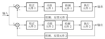
1、Single feedback and single correction synchronization control
As shown in Fig. 8, a single feedback control is applied to each of the two actuators so that the outputs of the actuators are all synchronized to track the set ideal output. The outputs of the two actuators are synchronized by tracking the set ideal output.
Fig. 8 Block diagram of single feedback single correction synchronization control
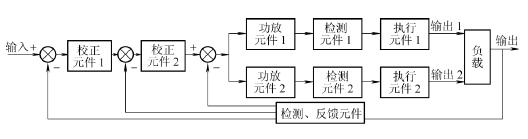
2、Common feedback and common correction synchronous control
As shown in Fig. 9, when two actuators are solidly connected to the load, a set of feedback detecting elements is used to measure the actual load's The actual state of motion of the load is measured by a set of feedback detection elements, and feedback control is implemented simultaneously on one or two actuators to track the set ideal output to achieve synchronization.
Fig. 9 Co-feedback co-correction synchronized control feedback block diagram
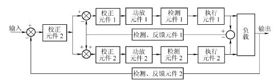
3, common feedback synchronization error correction synchronization control as shown in Figure 10, it is based on a single branch of the best tracking control _ to be synchronized with the output of the drive as a tracking target, through the feedback control so that the tracking error is minimized, and the use of the output synchronization error of the two actuators were synchronized compensation control.
Fig. 10 Block diagram of synchronization control with common feedback synchronization error correction
Third, different feedback, detection components composed of synchronous closed-loop control system
1、Servo valve
Servo valves can be divided into electro-hydraulic servo valves and electro-hydraulic servo valves. The former will mechanically feedback the piston position error to the servo valve, the servo valve of the follow-on adjustment of the flow to achieve synchronization of the two cylinders; the latter will be the position of the piston with an electrical signal feedback to the servo valve. Electro-hydraulic servo valve is a high-precision, high-frequency electro-hydraulic control element. The hydraulic synchronization closed-loop control system composed of it not only has a high response speed, but also high synchronization control accuracy. However, because of the complex structure and cost of this type of valve, it is not easy to control.
High and poor anti-pollution ability, so the hydraulic synchronous closed-loop control composed of electro-hydraulic servo valves is generally suitable for occasions requiring high synchronization accuracy.
2. Proportional valve
The proportional valve is a control method between the on-off control of ordinary hydraulic valves and the servo control of electro-hydraulic servo valves. It can realize the change of the pressure and flow of the liquid flow continuously and proportionally following the control signal. Its control performance is excellent. Because of the on-off control, the control accuracy and response speed are lower than the electro-hydraulic servo control, but its cost is low, the anti-pollution ability is strong, and it is easy to realize computer control. Therefore, the closed-loop control system composed of it has been widely used in occasions where the system frequency response is moderate and high synchronization accuracy is required.
3. Digital valve
The digital valve is an electromechanical-hydraulic integrated control component that was gradually developed in the early 1980s. Its biggest feature is that it can adapt to the needs of computer control and directly realize control with digital quantities, eliminating the need for D/A converters that are necessary in general computer control systems. In addition, the valve has high anti-pollution ability. Therefore, the hydraulic synchronous closed-loop control system composed of it has the advantages of convenient control, high reliability, high repeatability, simple structure, and easy realization of computer direct control. However, the synchronous control accuracy of this control form is affected by the pulse number, pulse width duty cycle and computer hardware and software of the stepper motor drive signal. 4. Synchronous motor synchronous circuit Among them, the throttling and speed regulating synchronous circuit (the synchronous circuit of the throttle valve and the speed regulating valve) belongs to the flow synchronous circuit, that is, the flow entering or flowing out of multiple hydraulic cylinders through the flow control valve makes the piston of the hydraulic cylinder The speed of movement is equal to achieve speed synchronization. Another synchronous loop, the volume synchronous loop, will be introduced below. The volume synchronization circuit refers to the distribution of two equal volumes of oil to two hydraulic cylinders of the same size to realize the synchronization of multiple hydraulic cylinders. This kind of circuit can allow a large eccentric load, the pressure difference caused by the eccentric load does not affect the change of the flow rate, but only affects the slight compression and leakage of the oil, the synchronization accuracy is high, and the system efficiency is also high. The volume synchronous circuit control components include a series oil cylinder with an oil replenishment device and a synchronous hydraulic cylinder. Due to the high manufacturing cost of these two methods, the error is large and the volume is large. The following introduces a method that uses multiple coaxial equal-displacement hydraulic motors as the oil distribution link to output the same oil to realize the synchronization of multiple hydraulic cylinders, just like the synchronous cylinder.
1. Classification of synchronous motors
Synchronous motor hydraulic synchronous system is divided into gear type synchronous motor system and plunger type synchronous motor system according to the type of synchronous motor used. The way to distinguish the two synchronous motors on the hydraulic schematic diagram is to see if the motor has oil leakage, and the plunger synchronous motor is generally marked with a special oil leakage port. The synchronous motor control system can be divided into two-cylinder synchronization and multi-cylinder synchronization according to the number of motor combinations. Compared with the gear synchronous motor and the plunger synchronous motor, the synchronization accuracy of the gear synchronous motor is much smaller than that of the plunger synchronous motor. The synchronization control accuracy of the plunger synchronous motor can reach more than 99%, while the synchronization accuracy of the gear synchronous motor is about 95%. %, and is greatly affected by the external load. Geared synchronous motors are relatively cheap and have low initial investment, and are widely used in multi-cylinder synchronous systems that do not require high precision. The hydraulic synchronization system of the plunger synchronous motor has high control precision, but the one-time investment is relatively large, and it is mostly used in double-cylinder and multi-cylinder synchronization systems that require high precision. The two motor synchronous control systems have certain requirements on the installation form and load of the oil cylinder. Try to use a horizontally installed hydraulic cylinder to use this synchronous system, because if you use this synchronous system with a hydraulic cylinder installed up and down, the external load of the oil cylinder is different. At this time, the output flow of the synchronous hydraulic motor will be slightly different, resulting in a large cumulative error when the hydraulic cylinder is in place, which will have a great impact on normal production, especially for the plunger type synchronous hydraulic motor control system.
The moving speed must not exceed the rated flow rate of the hydraulic motor, otherwise it will cause damage to the rotor bearing of the hydraulic motor.
2. Application of hydraulic synchronous motor
There are three main aspects of hydraulic synchronous motor applications:
1) As a flow balance device, operate multiple cylinders or motors synchronously
If several motors or hydraulic cylinders are supplied by the same oil source and work in parallel, and there is no control in any way on each branch, then the one bearing the smallest load will start the working cycle first, and its stroke will be completed. The second smallest load starts to work, and so on. However, this working mode is usually not the required mode, so it is necessary to divide the total pump flow into a series of partial flows, so that several motors or hydraulic cylinders working in parallel can be turned on at the same time and reach the designated position at the same time. The hydraulic synchronous motor is responsible for this. an important role.
2) As a flow distribution device, distribute the output flow of the pump according to the system requirements
Example: Shafts with multiple sets of friction bearings require that each bearing be supplied with the same amount of lubricant. Geared hydraulic motors do not have any external leakage, if one part of the gears is rotating, the same flow will pass through the other parts. Then it is only necessary to use an electronic speed sensor to detect the speed of a shaft in the shunt motor, and this problem can be solved smoothly.
3) As a booster device, the pressure at an output port of the diverter exceeds the output pressure of the pump
The hydraulic synchronous motor, in addition to being used as a "synchronous element", can also be used as a "supercharger". Because of its low cost and small internal pressure loss, it is often used as the best substitute for a "supercharger". This section summarizes that when the hydraulic synchronous closed-loop control system is used in the form of proportional valves, servo valves, and synchronous motors, the output of the actuator can be detected, fed back, and compared with the input signal to form a negative feedback closed-loop control.


 8617862265069
  info@cndieselpart.com
  English