Section Application of hydraulic synchronization technology
1. Water conservancy industry: hydraulic hoist synchronous control system
1. Synchronous control principle of hydraulic hoist (bypass oil discharge circuit)
The hydraulic system has a dual-cylinder door opening and closing synchronous deviation correction function to meet the requirements of synchronous operation of the gate.
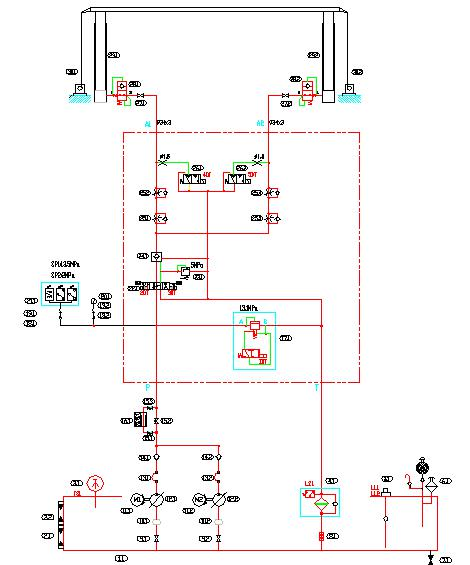
As shown in Figure 11, the hydraulic system divides the main oil circuit into two oil cylinders on both sides of the gate through two sets of speed regulating circuits, and controls the basic synchronization of the oil cylinders on both sides by controlling the oil in and out of the two oil cylinders. Due to the uncertain factors during the operation of the gate, the cylinders on both sides of the gate are not synchronized. At this time, it is necessary to rely on the bypass correction system to adjust the amount of oil in and out of the cylinders on both sides, so as to maintain the synchronization of the cylinders on both sides.
Through the gate opening detection device, the stroke of the left and right cylinders during the up and down operation (that is, the opening and closing height of the gate) is automatically detected, and the detected signal is sent to the PLC.
According to the signal sent by the gate opening detection device, the PLC compares the size and polarity of the out-of-sync error signals of the cylinders on both sides. When the out-of-sync error exceeds the programmed value, the PLC outputs a switch control signal to control the bypass correction system.
When the bypass correction system receives the correction signal from the PLC, the bypass correction system drains oil from a relatively high cylinder during the gate opening and closing operation, thereby controlling the stroke difference between the two cylinders and eliminating the deviation. After the oil is discharged, when the stroke (gate height) of the oil cylinders on both sides reaches the set value, the PLC sends a signal to stop the deviation correction.
At this time, the entire correction procedure is completed. This process is tracked throughout the process to ensure that the opening and closing of the two oil cylinders are synchronized, and the deviation is within the set range.
The electrical control system is also equipped with a deviation correction jog button. When the automatic synchronization deviation is greater than the maximum set value and causes a shutdown, the operator uses the "jog" control function in the local control unit to implement manual deviation correction to achieve synchronization.
The action description is as follows:
Open the gate: start the hydraulic pump motor unit with no load, delay for about 10 seconds, the solenoid valves 1DT and 2DT are energized, and the pressure oil enters the left and right hydraulic cylinder chambers through the reversing valve 22 in two routes, 25 and * speed control valves, and then synchronized with coarse adjustment , to lift the gate.
Close the gate: start the hydraulic pump motor unit without load, delay about 10 seconds, the solenoid valves 1DT and 3DT are energized, and the pressure oil passes through the reversing valve 22 to open the hydraulic control check valve, and the oil in the two oil cylinders is divided into two paths through 25 and 25. * After the coarse adjustment of the speed control valve is synchronized, the flow returns to the fuel tank through the reversing valve.
Gate synchronous control: During the opening and closing process of the gate, the gate opening and stroke control device continuously detects the stroke deviation of the two hydraulic cylinders throughout the whole process. When the deviation value is ≥ 20mm, the solenoid valve 4DT or 5DT is automatically energized, and the hydraulic cylinder is adjusted. When the amount of oil output is such that the synchronous deviation of the two cylinders reaches 10mm, the deviation correction adjustment stops. When the stroke deviation of the two hydraulic cylinders is ≥30mm, the hydraulic system will automatically stop and send out an alarm signal.
Gate automatic reset: When the gate sinks 150mm due to leakage of the hydraulic system at the fully open position, the travel control device instructs the hydraulic pump motor unit to start and automatically lifts the gate to the fully open position. When the sinking of the gate reaches 200mm due to a hydraulic pump failure, the stroke control device instructs the standby hydraulic pump motor unit to start, lift the gate to the fully open position, and send out an alarm signal at the same time.
Gate hydraulic system pressure protection: When SP1 sends a signal, it indicates that the working pressure of the hydraulic system is too high, there should be sound and light alarm, and the pump should be stopped for maintenance. When SP2 sends a signal, it indicates that the hydraulic pump is working abnormally, and there should be an audible and visual alarm, start the backup pump or stop the pump for maintenance
Electrical control of the fuel tank: When LS1 sends out a signal, it indicates that the oil filter is blocked, and there should be an audible and visual alarm to remind you to clean or replace the filter element. When TS1 sends a signal, it indicates that the temperature of the fuel tank is too high, and there should be an audible and visual alarm. When LL1 sends a signal, it indicates that the liquid level of the fuel tank is too high, and there should be sound and light alarm, and the pump should be stopped for maintenance. When LL2 sends a signal, it indicates that the liquid level of the fuel tank is too low, and there should be an audible and visual alarm, and the pump should be stopped for maintenance.
Figure 11 Hydraulic opener system schematic
During the operation of the hydraulic hoist, there will inevitably be a difference between the two piston rods due to the influence of many factors (inside the hydraulic system and outside the system). In order to ensure the safe operation of the gate, the stroke difference between the two piston rods must be controlled within Within a certain range, a synchronous correction circuit for flow control is set in the hydraulic system for this purpose. The types of synchronous rectification circuits used for flow control include bypass oil discharge circuit (as shown in Figure 8), proportional speed control valve circuit, servo valve circuit and proportional variable pump circuit. bypass
The two forms of oil discharge circuit and proportional speed control valve circuit are more commonly used.
The bypass oil discharge circuit is controlled by switch, which belongs to open-loop control. The main problem of this circuit is that the frequent and sudden opening and closing of the electromagnetic valve that plays the role of oil discharge in the system will cause sudden changes in the pressure of the hydraulic system, which will cause vibration and noise in the system. Its direct consequence is: affect the accurate detection of piston rod stroke and stroke difference, also will cause the opening degree of hydraulically controlled one-way valve in cylinder side valve group to be unstable. In order to avoid or reduce the pressure shock to the system caused by the sudden opening or closing of the oil discharge solenoid valve, a pressure reducing valve or a throttle valve should be installed in front of the solenoid valve of the oil discharge circuit. In view of the above reasons, if the bypass oil discharge circuit is used as a synchronous deviation correction, the set deviation correction start value should be large rather than small under the premise of satisfying the safe operation of the gate, so as to reduce the switching times of the solenoid valve in the oil discharge circuit . The system is simple and requires less investment, but the adjustment value of the deviation correction is large, the system pressure is unstable (improved by adding a throttle valve), and there is a certain amount of energy consumption.
2、Proportional speed control valve circuit
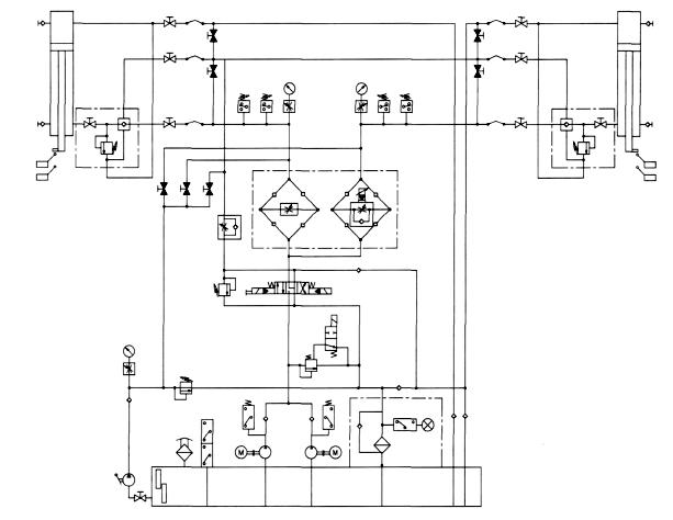
Figure 12 Proportional speed control valve circuit layout
The proportional speed regulating valve circuit belongs to proportional control, which is generally used for open-loop control, but it can also be used for closed-loop control. The schematic diagram of the hydraulic system using the proportional speed regulating valve circuit as the synchronous deviation correction is shown in Figure 12. When the stroke detection device detects that the stroke difference of the piston rods of the two oil cylinders reaches the set deviation correction adjustment value, the electrical control system will change the current value of the proportional electromagnetic coil originally supplied to the proportional speed regulating valve, that is, change the hydraulic system supply 2 The flow rate ratio of each oil cylinder, so as to achieve the purpose of synchronous deviation correction. The starting value of its deviation correction can be determined according to the accuracy of the stroke detection device selected and the control requirements of the gate.
The main features of this circuit are: continuous proportional electric-hydraulic control is possible, and its control accuracy and speed response are higher than those of the bypass oil discharge circuit; its set deviation correction start-up value is relatively small; the system pressure is stable; no energy consumption; The investment is larger than that of the bypass oil discharge circuit. To achieve closed-loop control, it is necessary to set feedback detection elements and corresponding electrical controls, so closed-loop control is more complicated than open-loop control.
Servo valve circuits are used in closed loop control systems. This loop is similar to the closed-loop control of the proportional speed regulating valve. Its main features are: high control precision, fast response speed, and strong ability to resist external interference; the structure of the servo valve is complex and precise, and the requirements for its processing, assembly and debugging are high; the pollution control requirements for the hydraulic system are extremely strict, and the corresponding electrical The control equipment is also complicated, the maintenance is difficult and the investment is large. Therefore, it has not been applied in hydraulic hoist so far.
2. Synchronization system of hydraulic lifting drilling rig
The hydraulic lifting synchronization system is designed for ZJ40DBST new 4 000 m hydraulic lifting fast transfer drilling rig. The base of the drilling rig is vertically lifted by 4 hydraulic cylinders, and the derrick of the drilling rig is lifted by rotation by 2 hydraulic cylinders. Synchronous motor, PLC, displacement sensor, etc. are selected and combined to design a synchronous control system, which ensures the synchronization of the hydraulic cylinder and the safety and reliability of the drilling rig under lifting and lowering conditions, and shortens the time for relocation and installation of the drilling rig.
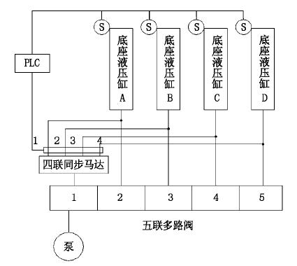
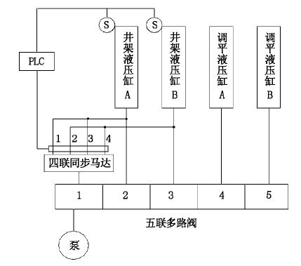
The hydraulic system for base lifting is shown in Figure 13. The hydraulic pump provides hydraulic power oil to operate the valve plate 1 of the five-way multi-way valve. The pressure oil is divided into equal parts by the four-way synchronous motor, and is supplied to the four base hydraulic cylinders A, B, C, and D to make them expand and contract synchronously with high precision. Monitored by PLC system. Operate the valve slices 2, 3, 4, and 5 of the five-way multi-way valve to individually control the hydraulic cylinders A, B, C, and D of the base. In the absence of PLC control, the telescopic strokes of the hydraulic cylinders 4 and 4 can be manually controlled. , synchronously lift and release the base.
The hydraulic system for derrick lifting is shown in Figure 14. The hydraulic pump provides hydraulic power oil to operate the valve section 1 of the five-way multi-way valve, and the pressure oil is equally divided by the four-way synchronous motor. Since there are only two derrick hydraulic cylinders, in order to share the synchronous motor, the four-way motors 1 and 3 are connected in parallel Oil is supplied to derrick hydraulic cylinder A, and quadruple motors 2 and 4 are connected in parallel to oil derrick hydraulic cylinder B, so that the two derrick hydraulic cylinders expand and contract synchronously, and the synchronization accuracy is monitored by the PLC system. Manipulating the valve plates 2 and 3 of the five-way multi-way valve can independently control the hydraulic cylinders A, B of the derrick. In the absence of PLC control, the telescopic stroke of the hydraulic cylinder can be manually controlled, and the derrick can be raised and lowered synchronously.
Figure 13 Hydraulic system for base lifting Figure 14 Hydraulic System for Derrick Lifting
Among the commonly used synchronous loops, the throttling synchronous loop is more commonly used. The throttling synchronization circuit is simple and low in cost, but the synchronization accuracy is greatly affected by the oil temperature and load, and the synchronization performance is poor. This system adopts a volumetric synchronous circuit, 4 hydraulic motors are mechanically connected through the same shaft, rotate at the same speed, and send the same flow to 4 hydraulic cylinders, thereby realizing the synchronization of the four cylinders. The synchronization accuracy of the volumetric synchronous circuit depends on the volumetric efficiency of the hydraulic motor. The pressure difference caused by the eccentric load does not affect the flow into the hydraulic cylinder, but only affects the slight compression and leakage.
When the base is raised and lowered, the hydraulic oil is divided into four by the synchronous motor, and the expansion and contraction of the four oil cylinders are controlled by equal flow; when the derrick is raised and lowered, the hydraulic oil is divided into two by the synchronous motor, and the expansion and contraction of the oil cylinders are controlled by the equal flow. When the base or derrick is being lifted, the PLC processes the signals collected by the sensors. The output controls the action of the corresponding compensation valve to achieve the effect of eliminating the displacement error.
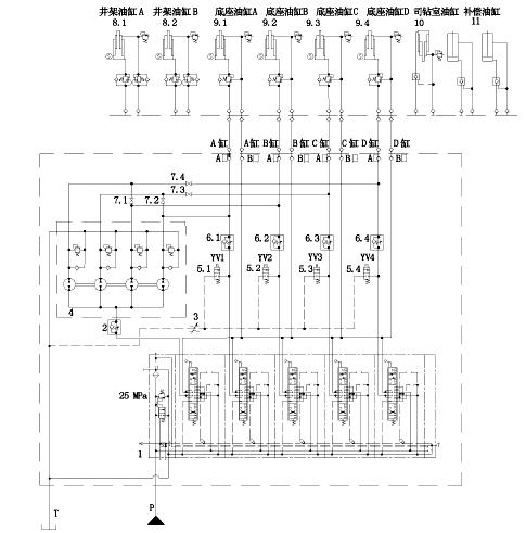
It is known that the rated flow rate of the drill pipe power tong is 114L/min, and the lifting load is 800KN, so the system flow rate is greater than 114L/min, and the lifting is performed by four oil cylinders at the same time, so the load of each oil cylinder is greater than 200KN, so the system pressure is set as 25MPa, its hydraulic schematic diagram is shown in Figure 15.
Summary of this section
Taking hoist and hoisting drilling rig in hydraulic conservancy as examples, the application of synchronous system is introduced.


 8617862265069
  info@cndieselpart.com
  English