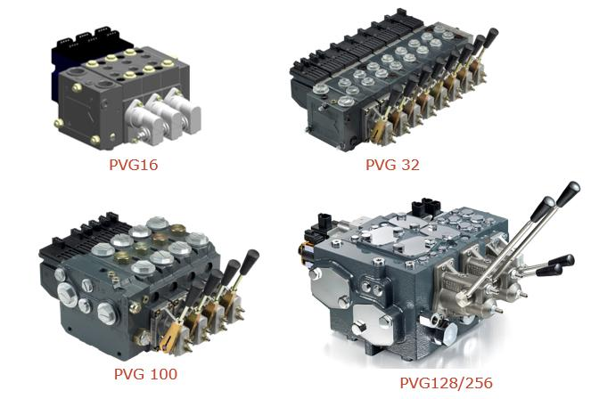
The PVG mainstream product line consists of the PVG16, PVG32, PVG100, and PVG128/256, with flow rates ranging from small to large.
The outline is shown in Figure:
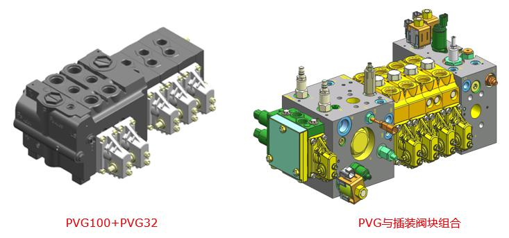
All PVG series are part of the same platform and can be combined across series to best meet application requirements. As shown in Figure.
As shown in Figure, such as PVG256+PVG128+PVG32+PVG16, or PVG100+PVG32, or PVG and cartridge block to form a manifold, there is a great deal of flexibility.
great flexibility.
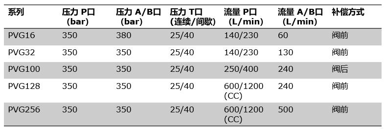
The entire PVG range is of high pressure design, rated at 350 bar, with flow sizes ranging from small to large, from 1L/min to 500L/min in the A/B port with compensator.
The flow rate of A/B port with compensator is 1L/min-500L/min, PVG100 is post-compensated, other series are pre-compensated.
PVG parameters:
Ⅱ. PVG Multi-Valve Structure
Just like LEGO, PVG multiplex valves also adopt a modular design concept, as can be seen from the exploded view below.
PVG manifold valves mainly consist of inlet link PVP, working link PVB, tail plate PVS, spool PVBS, compensator, manual module PVM, control module (PVE/PVH/PVG) and control module (PVE/PVH/PVG).PVM, control module (PVE/PVH/PVHC/PVMD), etc., as shown in Figure.
Many functions can be integrated into each function block, such as pilot operated pressure reducing valve, pressure limiting valve, Ls unloading valve (optional), and Ls unloading valve (optional) in the inlet link PVP. Ls unloading valve (optional), etc., and buffer valve PVLP, secondary pressure limiting valve (LsA/B), etc., can be integrated in the operating link.
Ⅲ.Flow Control Spools (FC Spools) and Pressure Spools (PC Spools)
1. Overview
In general, most applications can use flow control spools (FC spools), i.e., spools with pre-/post-valve compensation, which are often seen in the market; however, in certain applications, system inertia may cause shock.
In general, most applications can use flow control spools (FC spools), which are often marketed as pre/post compensated spools; however, in certain applications where system inertia may cause oscillations that can affect the safe operation of equipment, pressure spools are used.
However, in certain applications, the inertia of the system can lead to oscillations that can affect the safe operation of the equipment, which can be inhibited by the proper use of pressure cartridges (PC cartridges).
2、Flow control valve core
Flow control spools, as shown in the upper panel of Fig. 8, are common in oscillating systems where system instability is common in high inertia systems.
A similar situation is illustrated in the example below:
At any given moment, the compensator is always working to maintain a consistent differential pressure across the main spool and to follow the actuator's feedback of
The compensator is always working to maintain a consistent differential pressure across the main spool at all times and follows the pressure oscillations fed back to the spool by the actuator. As the load pressure changes, the compensator will follow at the same frequency, allowing the valve to deliver a constant flow.
The flow control spool therefore provides a constant flow rate. Thus the flow control spool provides a constant flow, but does not provide vibration dampening.
3、Pressure control valve spool (PC spool)
Pressure control spool (PC spool) Danfoss introduced the PVG32 pressure control spool (PC spool) in the 1990s to overcome pressure instability and better control the opening of the balance valve.
(PC spool) in the 1990s to overcome pressure instability and to better control the opening of the counterbalance valve. Pressure control spools also use a variable
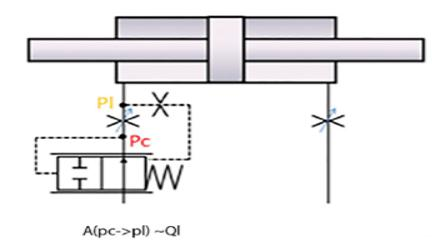
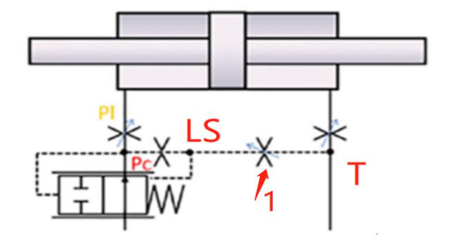
The pressure control spool also uses a variable orifice to regulate the flow of P-A/B and A/B-T, but with the addition of an Ls-T control loop, whereby by actuating the spool, the Ls-T pressure will be adjusted through a fixed and variable orifice.
By actuating the spool, the Ls pressure is fed back through a fixed and variable orifice. See schematic below: Pressure Control Spool (PC Spool) Basic Principle as shown in Figure.
principle as shown:
4、Pressure control spool and counterbalance valve
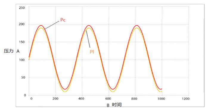
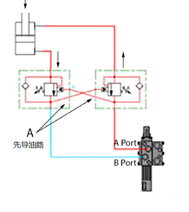
As shown in the diagram, the pressure spool is even more advantageous when a counterbalance valve is used to control the load. The counterbalance valve will open in a controlled manner under A
The counterbalance valve will open in a controlled manner under A port pressure. If a pressure control spool is used in conjunction with a counterbalance valve, the Pc pressure is proportional to the spool position.
If a pressure control spool is used, the Pc pressure is proportional to the spool position, and the counterbalance valve will eventually open in proportion to the spool position. If a flow control spool is used, the spool stroke is fixed.
If a flow spool is used, the spool stroke is fixed, the flow rate at the port is fixed, and the counterbalance valve at port B can be opened when the pressure rises to a certain value.
When the load accelerates and drops, the pressure in port A will decrease, and when the pressure falls below the value required for pilot control, the counterbalance valve cannot be opened. The counterbalance valve will not be opened when the pressure falls below the required value for pilot control.
The counterbalance valve switches between opening and closing, causing the system to become unstable and to oscillate downward.
5. SUMMARY
Most applications can be controlled with flow spool valves that provide load independent flow control. In certain
specific applications where it is determined that the system will have or has had stability problems, a PVG pressure spool can be used instead of a traditional flow spool.
PVG pressure spools can be used in place of conventional flow spools in specific applications where it has been determined that the system will have or has had stability problems, minimizing most of the oscillations. Where a counterbalance valve is used to control the load, a pressure spool can
Pressure spools can provide great value when used to control loads with counterbalance valves, and combinations of pressure and flow spools can provide excellent control performance for specific applications.
The combination of pressure and flow spools can provide excellent control performance for specific applications.


 8617862265069
  info@cndieselpart.com
  English