The speed-up circuit refers to the circuit that increases the speed of the actuator without increasing the flow rate of the hydraulic pump. Common methods include self-weight oil replenishment, auxiliary cylinders, speed-increasing cylinders, differential cylinders, and accumulators.
Ⅰ.Self-weight oil replenishment speed-up circuit
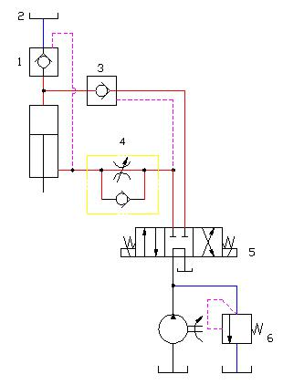
When the right position of the manual reversing valve 5 intervenes in the circuit, the piston descends rapidly due to the self-weight of the moving parts, and its descending speed is controlled by the one-way throttle valve 4. At this time, due to the insufficient oil supply of the hydraulic pump, negative pressure will appear in the upper chamber of the hydraulic cylinder. Add oil to the upper chamber of the hydraulic cylinder; when the moving parts contact the workpiece and cause the load to increase, the pressure in the upper chamber of the hydraulic cylinder increases, and the filling valve 3 is closed. At this time, only the hydraulic pump supplies oil to reduce the movement speed of the piston. During the return stroke, the left position of the reversing valve 5 is connected to the circuit, and the pressure oil enters the lower chamber of the hydraulic cylinder, and at the same time, the charging valve 1 is opened, and the oil returned from the upper chamber of the hydraulic cylinder enters the liquid-filled oil tank2. In order to prevent insufficient oil absorption in the upper chamber of the hydraulic cylinder when the piston descends rapidly, the liquid-filled oil tank is often replaced by a pressure oil tank to realize forced liquid filling. This type of circuit is used in hydraulic press systems where the mass of the vertically moving parts is high. For horizontal hydraulic cylinders, the weight of moving parts cannot be used for rapid movement. Later, the differential cylinder and speed-increasing cylinder will be introduced, which are the application of horizontal hydraulic cylinder speed-up.
Ⅱ. the speed-increasing circuit with a low-pressure pump
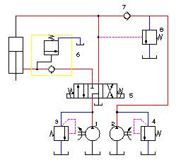
In Fig. 2, both the low-flow high-pressure pump 2 and the high-flow low-pressure pump 1 are unloaded through the reversing valve 5. When the piston is lowered, that is, when the reversing valve 5 is switched to the right position, the two pumps supply oil to the piston chamber of the cylinder at the same time to realize rapid movement. When the hydraulic cylinder (moving part) touches the workpiece, the pressure in the piston chamber of the hydraulic cylinder increases, and the unloading valve 8 is opened to unload the pump 1, the oil pump 2 supplies oil alone, and the piston turns to a slow pressurization process. As the piston rises, only the small flow oil pump 2 supplies oil. In order to ensure that the rising speed is fast enough, the area of the upper chamber of the piston of the oil cylinder is more than three times the area of the piston rod chamber of the oil cylinder. This circuit is suitable for presses with large mass of moving parts and large speed values.
Fig. 2 Circuit to increase speed with low pressure pump
Ⅲ. Differential speed connection speed-up circuit
1. The concept of differential connection
Differential connection is generally to connect the oil inlet and oil return of the hydraulic cylinder together, and return the oil hydraulically from the rod chamber of the cylinder to the rodless chamber to increase the speed at which the hydraulic cylinder protrudes outward. This connection method is generally used in In the fast-moving process with no load or small load, it increases the speed of motion at the expense of output force.
A differential circuit is a commonly used fast acting circuit. When quick action is required, the return oil from the rod chamber of the hydraulic cylinder flows into the rodless chamber through the P-type working function of the reversing valve or the combination of valves, thereby increasing the flow into the rodless chamber and pushing the piston to move quickly. In this connection form, because the pipeline is arranged outside the hydraulic cylinder, it is called external differential. Under the condition of certain pressure and load, pipeline resistance is the decisive factor restricting the speed of piston movement. Therefore, the external differential hydraulic cylinder is generally only suitable for occasions with short strokes and short and simple external connecting pipelines. For hydraulic cylinders with long strokes, due to the long external connecting pipeline, the indispensable elbows and pipe joints cause greater fluid flow resistance, so it is difficult to achieve the desired rapid action.
2. The structure of the inner differential hydraulic cylinder
There are many structures of differential hydraulic cylinders, but the most suitable for hydraulic impact equipment is the inner differential hydraulic cylinder with the simplest structure. In the past ten years, there are roughly three types of internal differential hydraulic cylinders designed and used for this purpose. The structure and principle are basically the same, each has its own characteristics, and is suitable for different occasions.
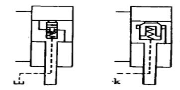
Figure 3a is a schematic diagram of the structure of the internal differential hydraulic cylinder with external leakage. The inner differential valve is a stepped slide valve. During fast movement, both the rodless chamber and the rod chamber are under high pressure, the valve core moves to the lower end under the action of the pressure oil, and the valve port is opened, so that the pressure oil in the rod chamber can flow into the rodless chamber smoothly, realizing the impact operation. In order to ensure reliable sealing of the two-chamber channels during the return stroke of the piston, the return spring of the spool must have a certain rigidity. Therefore, when the internal differential is to be realized, the corresponding slide valve opening pressure must be maintained in the cylinder.
2) External control internal differential hydraulic cylinder
Figure 3b is a schematic diagram of the structure of the externally controlled internally differential hydraulic cylinder. The difference from the above is that the external leakage oil circuit is changed to the external control oil circuit, and the internal differential valve can use ordinary cartridge valves, and the opening pressure is also small. When the control oil circuit is connected to the oil tank, the spool moves down under the action of the pressure oil to open the valve port, leading to the two chambers of the hydraulic cylinder, and connecting them into an internal differential form. When the control oil circuit is connected with pressure oil, the valve port is closed, and it is in the state of ordinary piston cylinder.
a. External leakage internal differential cylinder
b. External control internal differential cylinder
3)Differential hydraulic cylinders without external leakage
The above two types of differential hydraulic cylinders have their own unique features, but the piston rod dragged on the external pipeline but some equipment for the Installation and use of inconvenience. In order to eliminate this "pigtail" and try to produce a one-way deformation body, instead of the original spring, effectively solve the problem of external leakage. Effectively solve the problem of external leakage
3、Application of internal differential hydraulic cylinder
Internal differential hydraulic cylinders have been effectively used in hydraulic piling machines, hydraulic shell driving machines, hydraulic forging machines and so on.
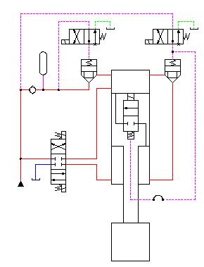
Fig. 4 shows the internal differential system of pile hammer of hydraulic pile driver (the hydraulic cylinder belongs to internal differential cylinder without external leakage).
When the hydraulic pile driver realizes the impact operation, the flow required in the rodless cavity is very large, and with the rapid fall of the hammer head, the oil demand increases sharply. Increase. Therefore, in addition to the hydraulic pump, accumulator at the same time to its oil supply, generally have an external differential circuit. But as analyzed above that Like, purely external differential circuit is far from being able to meet the needs of the rod chamber rapid oil discharge, so open the main channel in the piston. Obviously, this is a shortcut. Most of the return oil from the rod chamber enters the rodless chamber through the internal differential valve on the piston, forming a kind of internal and external oil discharge to the rodless chamber at the same time. A kind of internal and external at the same time to the rodless cavity oil discharge composite differential form (simplify the structure of the impact equipment), greatly accelerating the hammer head greatly accelerates the movement speed of the hammer head.
Fig. 4 Differential system within the pile hammer of a hydraulic pile driver
Summary of this section
This section describes the incremental speed control system in the form of an example of changeover control of speed, describing the oil replenishment by self-weight, low-pressure pumps, and differential speeds to enable the actuator to achieve a speed increase.


 8617862265069
  info@cndieselpart.com
  English